RT-Thread Studio-based USB Device Driver Development Document
Introduction
USB refers to Universal Serial Bus, it is a universal serial bus that supports hot-swap and is divided into USB Host and USB Device in the USB system. This article will take the stm32l475-atk-pandora development board as an example to introduce the development of the USB Device that based on RT-Thread Studio.
The development of the USB Device driver can be summarized in the following steps:
- Create an RT-Thread Standard Version project.
- Enable the
USB Devicedriver framework and configure the relevant sub-classes. - Define related macros of the
USB Deviceonboard.h. - Initialize the pin and peripheral clock of the
USB Deviceonboard.c. - Open HAL Library support for the
USB Deviceinstm32xxxx_hal_config.h.
For more details about USB Device configuration and addition processes please refer to the introduction of the USB Device in the corresponding project file board.h.
Create RT-Thread Project
Using RT-Thread Studio to create an RT-Thread v4.0.2 project, as shown below:
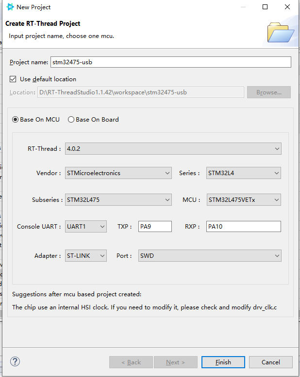
The configuration process can be summarized as follows:
- Define your own project name and the storage path for the generated project files.
- Select 'Base on MCU' to create a project and select RT-Thread version v4.0.2.
- Select the vendor and chip series.
- Configure serial information.
- Configure the debugger information.
Once the project is configured, click the 'Finish' button to create the RT-Thread project.
Enable USB Device Driver Framework
Configure USB Device in RT-Thread Settings, the configuration path is shown as below:
Components
---- Device Driver Program
--------Use USB
------------Use USB Device
----------------Select Device Type
In this example, the USB Device is configured as a CDC sub-class, a virtual serial port, as shown below:
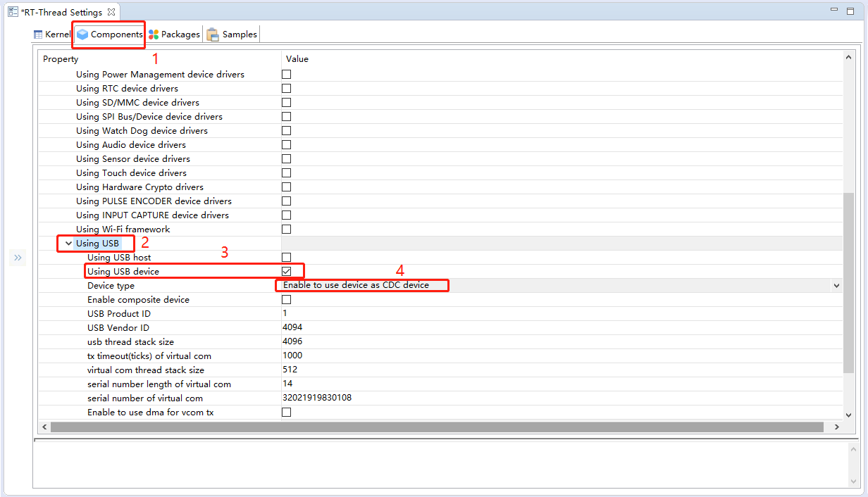
The virtual serial port properties and other information is configured by default. You can modify it according to your requirements.
Define Macros of USB Device
Navigate to the USB Device configuration instructions on board.h, define the related macros of BSP_USING_USBDEVICE according to the comments as follows:
#define BSP_USING_USBDEVICE
Initialize Pins and Clocks
Once the BSP_USING_USBDEVICE macro is defined, the drv_usbd.c file will start compiling, this file has only simply configured how the USB Device works and function transfers, the initialization of the clock and pins for USB Deviceneeds the help of the code generated in STM32CubeMx.
Copy the initialization code of the USB Device pin and clock that is generated by STM32CubeMx(typically stored in stm32_xxxx_hal_msp.c file) to the bottom of the board.c file of your own project for compiling, as shown below:
void HAL_PCD_MspInit(PCD_HandleTypeDef* hpcd)
{
  GPIO_InitTypeDef GPIO_InitStruct = {0};
  if(hpcd->Instance==USB_OTG_FS)
  {
  /* USER CODE BEGIN USB_OTG_FS_MspInit 0 */

  /* USER CODE END USB_OTG_FS_MspInit 0 */

    __HAL_RCC_GPIOA_CLK_ENABLE();
    /**USB_OTG_FS GPIO Configuration
    PA11     ------> USB_OTG_FS_DM
    PA12     ------> USB_OTG_FS_DP
    */
    GPIO_InitStruct.Pin = GPIO_PIN_11|GPIO_PIN_12;
    GPIO_InitStruct.Mode = GPIO_MODE_AF_PP;
    GPIO_InitStruct.Pull = GPIO_NOPULL;
    GPIO_InitStruct.Speed = GPIO_SPEED_FREQ_VERY_HIGH;
    GPIO_InitStruct.Alternate = GPIO_AF10_OTG_FS;
    HAL_GPIO_Init(GPIOA, &GPIO_InitStruct);

    /* Peripheral clock enable */
    __HAL_RCC_USB_OTG_FS_CLK_ENABLE();

    /* Enable VDDUSB */
    if(__HAL_RCC_PWR_IS_CLK_DISABLED())
    {
      __HAL_RCC_PWR_CLK_ENABLE();
      HAL_PWREx_EnableVddUSB();
      __HAL_RCC_PWR_CLK_DISABLE();
    }
    else
    {
      HAL_PWREx_EnableVddUSB();
    }
    /* USB_OTG_FS interrupt Init */
    HAL_NVIC_SetPriority(OTG_FS_IRQn, 0, 0);
    HAL_NVIC_EnableIRQ(OTG_FS_IRQn);
  /* USER CODE BEGIN USB_OTG_FS_MspInit 1 */

  /* USER CODE END USB_OTG_FS_MspInit 1 */
  }
}
Configure USB Peripheral Pins and Clocks
When using RT-Thread Studio to automatically generate projects, some peripheral clocks are not enabled by default in the system clock initialization function SystemClock_Config in board.c file. When these peripherals need to be used, you also need to initialize the peripheral clock with the help of the code generated by STM32CubeMX.
In this example, you need to use the USB peripheral, configure the system clock with the STM32CubeMX tool, and replace the SystemClock_Config function on the board.c file with the function you generated for your project from STM32CubeMX, as follows:
void SystemClock_Config(void)
{
  RCC_OscInitTypeDef RCC_OscInitStruct = {0};
  RCC_ClkInitTypeDef RCC_ClkInitStruct = {0};
  RCC_PeriphCLKInitTypeDef PeriphClkInit = {0};

  /** Configure LSE Drive Capability
  */
  HAL_PWR_EnableBkUpAccess();
  __HAL_RCC_LSEDRIVE_CONFIG(RCC_LSEDRIVE_LOW);
  /** Initializes the CPU, AHB and APB busses clocks
  */
  RCC_OscInitStruct.OscillatorType = RCC_OSCILLATORTYPE_LSI|RCC_OSCILLATORTYPE_HSE
                              |RCC_OSCILLATORTYPE_LSE;
  RCC_OscInitStruct.HSEState = RCC_HSE_ON;
  RCC_OscInitStruct.LSEState = RCC_LSE_ON;
  RCC_OscInitStruct.LSIState = RCC_LSI_ON;
  RCC_OscInitStruct.PLL.PLLState = RCC_PLL_ON;
  RCC_OscInitStruct.PLL.PLLSource = RCC_PLLSOURCE_HSE;
  RCC_OscInitStruct.PLL.PLLM = 1;
  RCC_OscInitStruct.PLL.PLLN = 20;
  RCC_OscInitStruct.PLL.PLLP = RCC_PLLP_DIV7;
  RCC_OscInitStruct.PLL.PLLQ = RCC_PLLQ_DIV2;
  RCC_OscInitStruct.PLL.PLLR = RCC_PLLR_DIV2;
  if (HAL_RCC_OscConfig(&RCC_OscInitStruct) != HAL_OK)
  {
    Error_Handler();
  }
  /** Initializes the CPU, AHB and APB busses clocks
  */
  RCC_ClkInitStruct.ClockType = RCC_CLOCKTYPE_HCLK|RCC_CLOCKTYPE_SYSCLK
                              |RCC_CLOCKTYPE_PCLK1|RCC_CLOCKTYPE_PCLK2;
  RCC_ClkInitStruct.SYSCLKSource = RCC_SYSCLKSOURCE_PLLCLK;
  RCC_ClkInitStruct.AHBCLKDivider = RCC_SYSCLK_DIV1;
  RCC_ClkInitStruct.APB1CLKDivider = RCC_HCLK_DIV1;
  RCC_ClkInitStruct.APB2CLKDivider = RCC_HCLK_DIV1;

  if (HAL_RCC_ClockConfig(&RCC_ClkInitStruct, FLASH_LATENCY_4) != HAL_OK)
  {
    Error_Handler();
  }
  PeriphClkInit.PeriphClockSelection = RCC_PERIPHCLK_RTC|RCC_PERIPHCLK_USART1
                              |RCC_PERIPHCLK_USART2|RCC_PERIPHCLK_USB
                              |RCC_PERIPHCLK_ADC;
  PeriphClkInit.Usart1ClockSelection = RCC_USART1CLKSOURCE_PCLK2;
  PeriphClkInit.Usart2ClockSelection = RCC_USART2CLKSOURCE_PCLK1;
  PeriphClkInit.AdcClockSelection = RCC_ADCCLKSOURCE_PLLSAI1;
  PeriphClkInit.RTCClockSelection = RCC_RTCCLKSOURCE_LSE;
  PeriphClkInit.UsbClockSelection = RCC_USBCLKSOURCE_PLLSAI1;
  PeriphClkInit.PLLSAI1.PLLSAI1Source = RCC_PLLSOURCE_HSE;
  PeriphClkInit.PLLSAI1.PLLSAI1M = 1;
  PeriphClkInit.PLLSAI1.PLLSAI1N = 12;
  PeriphClkInit.PLLSAI1.PLLSAI1P = RCC_PLLP_DIV7;
  PeriphClkInit.PLLSAI1.PLLSAI1Q = RCC_PLLQ_DIV2;
  PeriphClkInit.PLLSAI1.PLLSAI1R = RCC_PLLR_DIV2;
  PeriphClkInit.PLLSAI1.PLLSAI1ClockOut = RCC_PLLSAI1_48M2CLK|RCC_PLLSAI1_ADC1CLK;
  if (HAL_RCCEx_PeriphCLKConfig(&PeriphClkInit) != HAL_OK)
  {
    Error_Handler();
  }
  /** Configure the main internal regulator output voltage
  */
  if (HAL_PWREx_ControlVoltageScaling(PWR_REGULATOR_VOLTAGE_SCALE1) != HAL_OK)
  {
    Error_Handler();
  }
}
Open Support for USB Device in HAL Library
Open support for USB Device in stm32_xxxx_hal_config.h file, which means cancel off the HAL_PCD_MODULE_ENABLED macro definition comments, as shown below:
#define HAL_PCD_MODULE_ENABLED
Usage
Once the above steps are done, compile the download program and enter the list_device command in the terminal, with the following results:

As we can see from the output information of the terminal, the USB Device, and the virtual serial device have been successfully registered in the system.
Open Device Manager on Windows and connect the USB Device on the board to your PC via a data cable, as shown below:
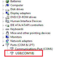
As we can see from the above image, the computer has successfully enumerated the virtual serial device configured above.