RT-Thread Studio-based Serial Driver Development Document
RT-Thread Standard Version serial driver development
Different from the serial port of the RT-Thread Nano version, the serial port of the RT-Thread Standard version is based on the device driver framework, and the serial port can use the rich components and packages provided by RT-Thread, such as AT components, Modbus packages, etc.
Configure the default serial port
Use RT-Thread Studio to create an RT-Thread v4.0.2 project, as shown below:
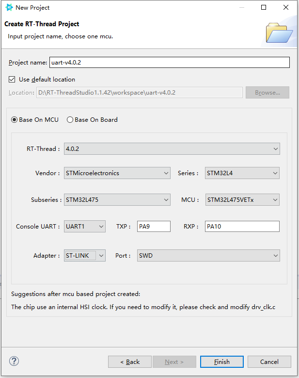
The configuration process can be summarized as follows:
- Define your own project name and the storage path for the generated project files.
- Select 'Base on MCU' to create a project and select RT-Thread v4.0.2.
- Select the vendor and chip series.
- Configure serial information.
- Configure the debugger information.
Once the project is configured, click the 'Finish' button to create the RT-Thread project. main.c file in the RT-Thread project will automatically generate the following code:
/* PLEASE DEFINE the LED0 pin for your board, such as: PA5 */
#define LED0_PIN    GET_PIN(A, 5)

int main(void)
{
    int count = 1;
    /* set LED0 pin mode to output */
    rt_pin_mode(LED0_PIN, PIN_MODE_OUTPUT);

    while (count++)
    {
        /* set LED0 pin level to high or low */
        rt_pin_write(LED0_PIN, count % 2);
        LOG_D("Hello RT-Thread!");
        rt_thread_mdelay(1000);
    }

    return RT_EOK;
}
Hello RT-Thread! is printed in the console at every 1000 ms in the code. After compiling and downloading the project, open the RT-Thread Studio serial tool can view the print information of the serial output, as shown below:
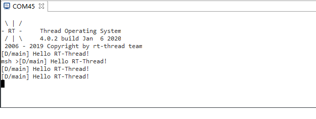
You can see from the serial output information that we have successfully used the serial output to print the information.
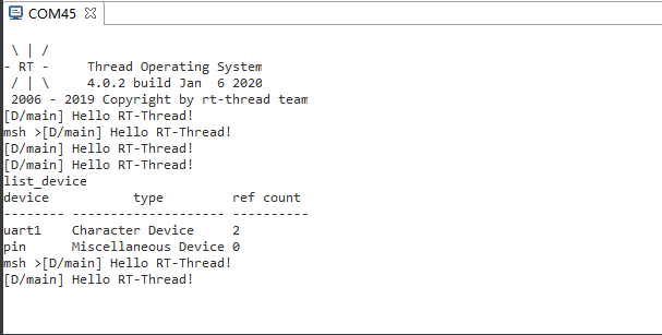
Enter list_device in the console to see that the uart1 device has been successfully registered in the system, as shown below:
Modify the default serial
As we can learn in the last section, the RT-Thread Studio graphical interface successfully configured the serial output, but some actual applications may need to use additional serial output information, which can be achieved by modifying some macro definitions and the RT-Thread Setting file.
Modify board.h macro
The board stm32l475-atk-pandora using UART1 to output by default, if change to UART2 (TX->PA2、RX->PA3), define the macro BSP_USING_UART2 in board.h and modify the fin information for serial 2 to the pin that actually used, as shown below:

The modification of the macro definition is divided into 2 main aspects.
- Modify the macro definitions corresponding to the serial port, such as
BSP_USING_UART1、BSP_USING_UART2and so on. - Modify the ports used by serial
TX/RX, such as"PA2"、"PA3"etc.
Modify RT-Thread Setting file
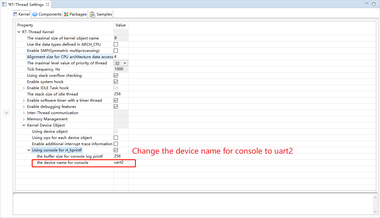
Modify the serial device name of the output console in the RT-Thread Setting file, as follows:
RT-Thread Setting
----Kernel
--------RT-Thread Kernel
------------Kernel Device Object
----------------Using Console for rt_kprintf
--------------------Console Name
The configuration is shown below:
Save the project configuration, compile and download, the serial output is shown in the following:

Enter the list_device command to view the registered devices, as shown below:
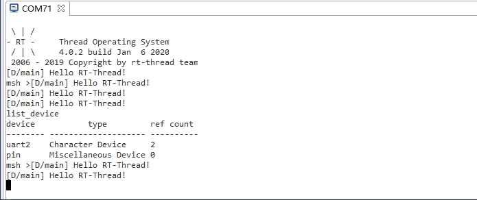
The information printed from the terminal shows that the serial device of the console has been successfully replaced from serial 1 to serial 2.
Add serial port
The new serial port only needs to define the macro definition BSP_USING_UARTx of the relevant serial port and modify the pin information in the board.h.
The steps for adding a serial port are summarized below.
- Add a macro definition for the corresponding serial port, such as BSP_USING_UART1, BSP_USING_UART2, etc.
- Modify the ports used by serial
TX/RX, such as"PA2"、"PA3"etc.
Here's an example to present the new serial 1 that added by modifying the console.

Compile and download the program, enter the list_device command in the console can see two serial devices are registered, serial 1 and serial 2. As shown below:
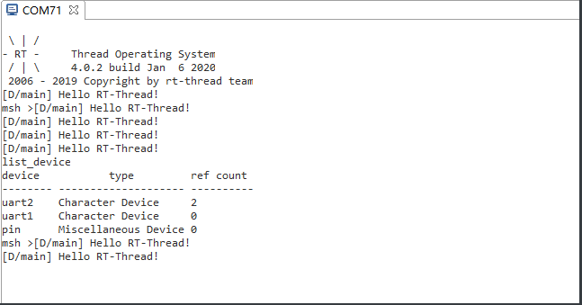
The information output from the console shows that both serial devices are registered to the system.
The usage of serial DMA
RT-Thread Settings configures DMA.
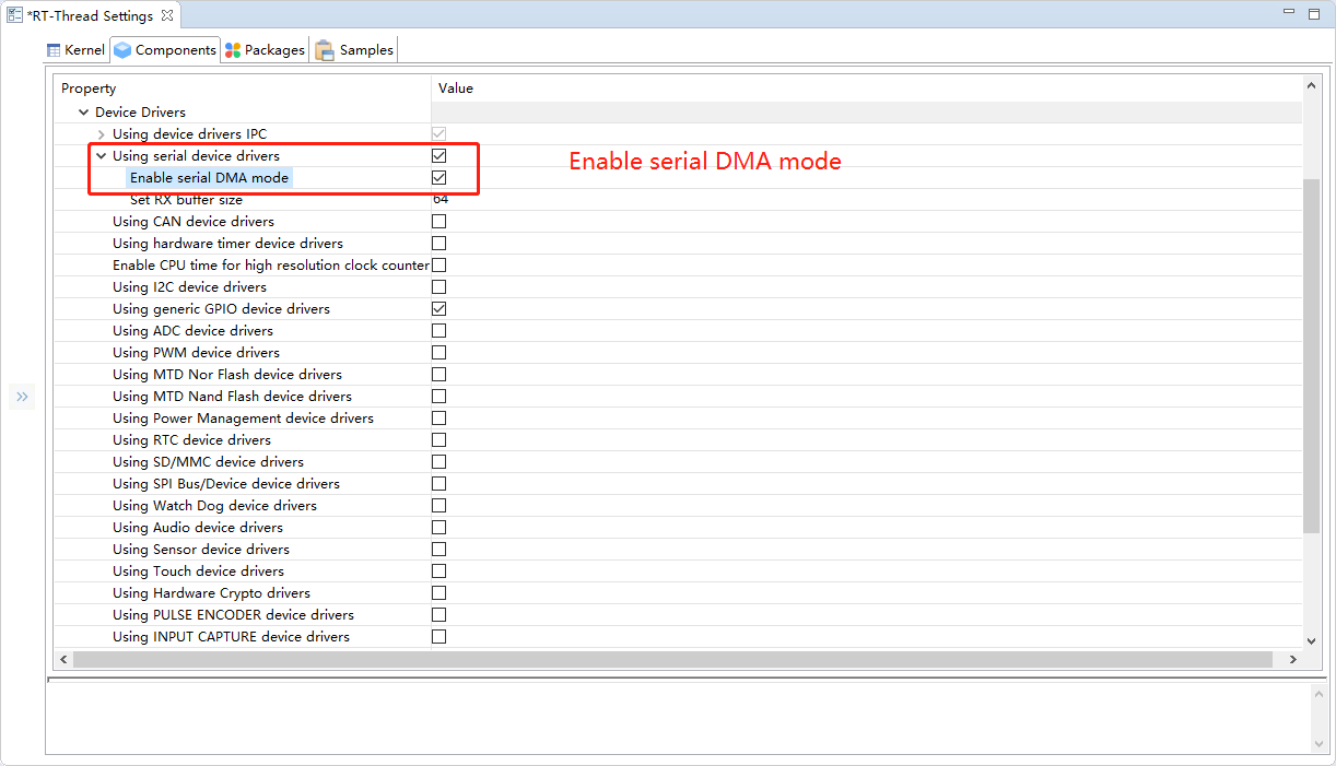
If you want to enable the features of serial DMA, you need to turn on DMA by using RT-Thread Setting. The configuration path is:
RT-Thread Setting
----Components
--------Device Driver
------------Use the UART device driver
----------------Enables serial DMA mode
The configuration process is shown below:
Configure macro in board.h
If you need to use serial DMA, you only need to define the following macros in the board.h file.
#define BSP_UARTx_RX_USING_DMA
#define BSP_UARTx_TX_USING_DMA
UARTxrepresents the serial port that requires DMA and the sending and receiving function of DMA is used. In this example, the DMA receiving function of serial port 2 is used, so the macroBSP_UART2_RX_USING_DMAis defined, the configuration of serial port 2 using DMA is shown below.

Add the DMA test code to the project.
Compile and download the program, enter the uart_dma_sample command in the console, and connect serial 2 using a USB cable, where you can see the following print information:
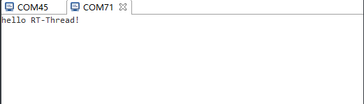
The test program using DMA to successfully receive the information.