PIN Device
Introduction of Pin
The pins on the chip are generally divided into four categories: power supply, clock, control, and I/O. The I/O port is further divided into General Purpose Input Output (GPIO) and function multiplex I/O (such as SPI/I2C/UART, etc.) in the usage mode.
Most MCU pins have more than one function. The internal structure of different pins is different and the functions are different. The actual function of the pin can be switched through different configurations. The main features of the General Purpose Input Output (GPIO) port are as follows:
- Programmable Interrupt: The interrupt trigger mode is configurable. Generally, there are five interrupt trigger modes as shown in the following figure:
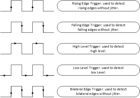
-
Input and output modes can be controlled.
-
Output modes generally include Output push-pull, Output open-drain, Output pull-up, and Output pull-down. When the pin is in the output mode, the connected peripherals can be controlled by configuring the level of the pin output to be high or low.
-
Input modes generally include: Input floating, Input pull-up, Input pull-down, and Analog. When the pin is in the input mode, the level state of the pin can be read, that is, high level or low level.
Access PIN Device
The application accesses the GPIO through the PIN device management interface provided by RT-Thread. The related interfaces are as follows:
| Function | Description |
|---|---|
| rt_pin_mode() | Set pin mode |
| rt_pin_write() | Set the pin level |
| rt_pin_read() | Read pin level |
| rt_pin_attach_irq() | Bind pin interrupt callback function |
| rt_pin_irq_enable() | Enable pin interrupt |
| rt_pin_detach_irq() | Detach pin interrupt callback function |
Obtain Pin Number
The pin numbers provided by RT-Thread need to be distinguished from the chip pin numbers. They are not the same concept. The pin numbers are defined by the PIN device driver and are related to the specific chip. There are two ways to obtain the pin number: use the macro definition or view the PIN driver file.
Use Macro Definition
If you use the BSP in the rt-thread/bsp/stm32 directory, you can use the following macro to obtain the pin number:
GET_PIN(port, pin)
The sample code for the pin number corresponding to LED0 with pin number PF9 is as follows:
#define LED0_PIN GET_PIN(F, 9)
View Driver Files
If you use a different BSP, you will need to check the PIN driver code drv_gpio.c file to confirm the pin number. There is an array in this file that holds the number information for each PIN pin, as shown below:
static const rt_uint16_t pins[] =
{
    __STM32_PIN_DEFAULT,
    __STM32_PIN_DEFAULT,
    __STM32_PIN(2, A, 15),
    __STM32_PIN(3, B, 5),
    __STM32_PIN(4, B, 8),
    __STM32_PIN_DEFAULT,
    __STM32_PIN_DEFAULT,
    __STM32_PIN_DEFAULT,
    __STM32_PIN(8, A, 14),
    __STM32_PIN(9, B, 6),
    ... ...
}
Take __STM32_PIN(2, A, 15) as an example, 2 is the pin number used by RT-Thread, A is the port number, and 15 is the pin number, so the pin number corresponding to PA15 is 2.
Set Pin Mode
Before the pin is used, you need to set the input or output mode first, and the following functions are used:
void rt_pin_mode(rt_base_t pin, rt_base_t mode);
| Parameter | Discription |
|---|---|
| pin | Pin number |
| mode | Pin operation mode |
At present, the pin working mode supported by RT-Thread can take one of the five macro definition values as shown. The mode supported by the chip corresponding to each mode needs to refer to the specific implementation of the PIN device driver:
#define PIN_MODE_OUTPUT 0x00            /* Output */
#define PIN_MODE_INPUT 0x01             /* Input */
#define PIN_MODE_INPUT_PULLUP 0x02      /* input Pull up  */
#define PIN_MODE_INPUT_PULLDOWN 0x03    /* input Pull down  */
#define PIN_MODE_OUTPUT_OD 0x04         /* output Open drain  */
An example of use is as follows:
#define BEEP_PIN_NUM            35  /* PB0 */

/* Buzzer pin is in output mode */
rt_pin_mode(BEEP_PIN_NUM, PIN_MODE_OUTPUT);
Set The Pin Level
The function to set the pin output level is as follows:
void rt_pin_write(rt_base_t pin, rt_base_t value);
| Parameter | Discription |
|---|---|
| pin | Pin number |
| value | Level logic value, which can take one of two macro definition values: PIN_LOW means low level, or PIN_HIGH means high level |
Examples of use are as follows:
#define BEEP_PIN_NUM            35  /* PB0 */

/* Beep's pin is in output mode */
rt_pin_mode(BEEP_PIN_NUM, PIN_MODE_OUTPUT);
/* Set low level */
rt_pin_write(BEEP_PIN_NUM, PIN_LOW);
Read Pin Level
The functions to read the pin level are as follows:
int rt_pin_read(rt_base_t pin);
| Parameter | Description |
|---|---|
| pin | Pin number |
| return | —— |
| PIN_LOW | Low level |
| PIN_HIGH | High level |
Examples of use are as follows:
#define BEEP_PIN_NUM            35  /* PB0 */
int status;

/* Buzzer pin is in output mode */
rt_pin_mode(BEEP_PIN_NUM, PIN_MODE_OUTPUT);
/* Set low level */
rt_pin_write(BEEP_PIN_NUM, PIN_LOW);

status = rt_pin_read(BEEP_PIN_NUM);
Bind Pin Interrupt Callback Function
To use the interrupt function of the pin, you can use the following function to configure a pin to some interrupt trigger mode and bind an interrupt callback function to the corresponding pin. When the pin interrupt occurs, the callback function will be executed. :
rt_err_t rt_pin_attach_irq(rt_int32_t pin, rt_uint32_t mode,
                           void (*hdr)(void *args), void *args);
| Parameter | Description |
|---|---|
| pin | Pin number |
| mode | Interrupt trigger mode |
| hdr | Interrupt callback function. Users need to define this function |
| args | Interrupt the parameters of the callback function, set to RT_NULL when not needed |
| return | —— |
| RT_EOK | Binding succeeded |
| error code | Binding failed |
Interrupt trigger mode mode can take one of the following five macro definition values:
#define PIN_IRQ_MODE_RISING 0x00         /* Rising edge trigger */
#define PIN_IRQ_MODE_FALLING 0x01        /* Falling edge trigger */
#define PIN_IRQ_MODE_RISING_FALLING 0x02 /* Edge trigger (triggered on both rising and falling edges)*/
#define PIN_IRQ_MODE_HIGH_LEVEL 0x03     /* High level trigger */
#define PIN_IRQ_MODE_LOW_LEVEL 0x04      /* Low level trigger */
Examples of use are as follows:
#define KEY0_PIN_NUM            55  /* PD8 */
/* Interrupt callback function */
void beep_on(void *args)
{
    rt_kprintf("turn on beep!\n");

    rt_pin_write(BEEP_PIN_NUM, PIN_HIGH);
}
static void pin_beep_sample(void)
{
    /* Button 0 pin is the input mode */
    rt_pin_mode(KEY0_PIN_NUM, PIN_MODE_INPUT_PULLUP);
    /* Bind interrupt, rising edge mode, callback function named beep_on */
    rt_pin_attach_irq(KEY0_PIN_NUM, PIN_IRQ_MODE_FALLING, beep_on, RT_NULL);
}
Enable Pin Interrupt
After binding the pin interrupt callback function, use the following function to enable pin interrupt:
rt_err_t rt_pin_irq_enable(rt_base_t pin, rt_uint32_t enabled);
| Parameter | Description |
|---|---|
| pin | Pin number |
| enabled | Status, one of two values: PIN_IRQ_ENABLE, and PIN_IRQ_DISABLE |
| return | —— |
| RT_EOK | Enablement succeeded |
| error code | Enablement failed |
Examples of use are as follows:
#define KEY0_PIN_NUM            55  /* PD8 */
/* Interrupt callback function */
void beep_on(void *args)
{
    rt_kprintf("turn on beep!\n");

    rt_pin_write(BEEP_PIN_NUM, PIN_HIGH);
}
static void pin_beep_sample(void)
{
    /* Key 0 pin is the input mode */
    rt_pin_mode(KEY0_PIN_NUM, PIN_MODE_INPUT_PULLUP);
    /* Bind interrupt, rising edge mode, callback function named beep_on */
    rt_pin_attach_irq(KEY0_PIN_NUM, PIN_IRQ_MODE_FALLING, beep_on, RT_NULL);
    /* Enable interrupt */
    rt_pin_irq_enable(KEY0_PIN_NUM, PIN_IRQ_ENABLE);
}
Detach Pin Interrupt Callback Function
You can use the following function to detach the pin interrupt callback function:
rt_err_t rt_pin_detach_irq(rt_int32_t pin);
| Parameter | Description |
|---|---|
| pin | Pin number |
| return | —— |
| RT_EOK | Detachment succeeded |
| error code | Detachment failed |
After the pin detaches the interrupt callback function, the interrupt is not closed. You can also call the bind interrupt callback function to bind the other callback functions again.
#define KEY0_PIN_NUM            55  /* PD8 */
/* Interrupt callback function */
void beep_on(void *args)
{
    rt_kprintf("turn on beep!\n");

    rt_pin_write(BEEP_PIN_NUM, PIN_HIGH);
}
static void pin_beep_sample(void)
{
    /* Key 0 pin is the input mode */
    rt_pin_mode(KEY0_PIN_NUM, PIN_MODE_INPUT_PULLUP);
    /* Bind interrupt, rising edge mode, callback function named beep_on */
    rt_pin_attach_irq(KEY0_PIN_NUM, PIN_IRQ_MODE_FALLING, beep_on, RT_NULL);
    /* Enable interrupt */
    rt_pin_irq_enable(KEY0_PIN_NUM, PIN_IRQ_ENABLE);
    /* Detach interrupt callback function */
    rt_pin_detach_irq(KEY0_PIN_NUM);
}
PIN Device Usage Example
The following sample code is the pin device usage example. The main steps of the sample code are as follows:
-
Set the corresponding pin of the beep to the output mode and give a default low state.
-
Set the key 0 and button 1 corresponding to the input mode, then bind the interrupt callback function and enable the interrupt.
-
When the key 0 is pressed, the beep starts to sound, and when the key 1 is pressed, the beep stops.
/*
 * Program listing: This is a PIN device usage routine
 * The routine exports the pin_beep_sample command to the control terminal
 * Command call format:pin_beep_sample
 * Program function: control the buzzer by controlling the level state of the corresponding pin of the buzzer by pressing the button
*/

#include <rtthread.h>
#include <rtdevice.h>

/* Pin number, determined by looking at the device driver file drv_gpio.c */
#ifndef BEEP_PIN_NUM
    #define BEEP_PIN_NUM            35  /* PB0 */
#endif
#ifndef KEY0_PIN_NUM
    #define KEY0_PIN_NUM            55  /* PD8 */
#endif
#ifndef KEY1_PIN_NUM
    #define KEY1_PIN_NUM            56  /* PD9 */
#endif

void beep_on(void *args)
{
    rt_kprintf("turn on beep!\n");

    rt_pin_write(BEEP_PIN_NUM, PIN_HIGH);
}

void beep_off(void *args)
{
    rt_kprintf("turn off beep!\n");

    rt_pin_write(BEEP_PIN_NUM, PIN_LOW);
}

static void pin_beep_sample(void)
{
    /* Beep pin is in output mode */
    rt_pin_mode(BEEP_PIN_NUM, PIN_MODE_OUTPUT);
    /* Default low level */
    rt_pin_write(BEEP_PIN_NUM, PIN_LOW);

    /* KEY 0 pin is the input mode */
    rt_pin_mode(KEY0_PIN_NUM, PIN_MODE_INPUT_PULLUP);
    /* Bind interrupt, falling edge mode, callback function named beep_on */
    rt_pin_attach_irq(KEY0_PIN_NUM, PIN_IRQ_MODE_FALLING, beep_on, RT_NULL);
    /* Enable interrupt */
    rt_pin_irq_enable(KEY0_PIN_NUM, PIN_IRQ_ENABLE);

    /* KEY 1 pin is input mode */
    rt_pin_mode(KEY1_PIN_NUM, PIN_MODE_INPUT_PULLUP);
    /* Binding interrupt, falling edge mode, callback function named beep_off */
    rt_pin_attach_irq(KEY1_PIN_NUM, PIN_IRQ_MODE_FALLING, beep_off, RT_NULL);
    /* Enable interrupt */
    rt_pin_irq_enable(KEY1_PIN_NUM, PIN_IRQ_ENABLE);
}
/* Export to the msh command list */
MSH_CMD_EXPORT(pin_beep_sample, pin beep sample);