Other Drivers Development Documents in RT-Thread Studio and STM32CubeMx
When you create an RT-Thread project using RT-Thread Studio, the RT-Thread real-time operating system is directly ported to the corresponding chip.
Using the STM32CubeMx configuration tool can quickly configure the clocks and pins of chip peripherals, making the development of drivers easy and simple.
This article will introduce driver development based on RT-Thread Studio and STM32CubeMx.
Note that the driver development we mentioned here is not based on the RT-Thread device driver framework, it is using the STM32CubeMx to generate the HAL library files for peripheral drivers development.
Introduction
Using the RT-Thread Studio and STM32CubeMx for drivers development can be divided into the following steps.
- Create an RT-Thread project using
RT-Thread Studio. - Configure peripherals and system clocks using
STM32CubeMx. - Copy the
stm32xxxx_hal_msp.cfunction. - Modify the
stm32xxxx_hal_config.hfile to enable the appropriate peripheral support. - Replace the clock configuration function on the
board.cfile. - Use peripherals.
Create RT-Thread Project
Using RT-Thread Studio to create an RT-Thread nano-v3.1.3 project, as shown below:
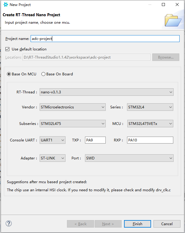
The configuration process can be summarized as follows:
- Define your own project name and the storage path for the generated project files.
- Select 'Base on MCU' to create a project and select RT-Thread version
nano-v3.1.3. - Select the vendor and chip series.
- Configure serial information.
- Configure the debugger information.
Once the project is configured, click the 'Finish' button to create the RT-Thread project.
Once the project is created based on RT-Thread Studio, you can develop your own drivers based on the projects you created. We'll take the example of the stm32l475-atk-pandora board to introduce how to develop ADC drivers.
Configure Peripherals
Create a CubeMx project based on the board and configure the peripherals you need to use.
For example, the PC2 of the board is connected to Channel 3 of ADC1, and the configuration results for the driver code of the ADC that generated by CubeMx are as follows:

Copy stm32xxxx_hal_msp.c Function
Copy the CubeMx generated code function stm32l4xx_hal_msp.c into the project generated by RT-Thread Studio to compile. The copy results are shown as follows:
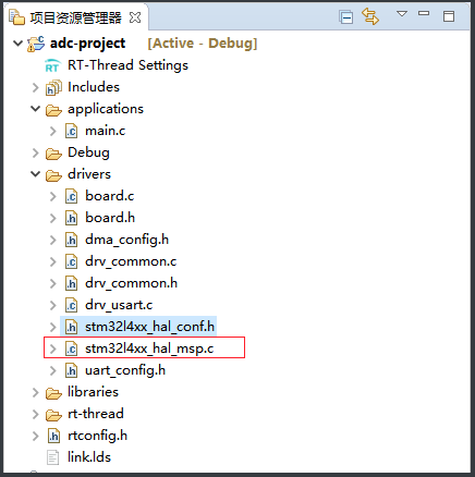
Since we don't use the CubeMx generated project, we need to replace the #include "main.h" with #include "board.h" in stm32l4xx_hal_msp.c file.
Open the Supported Macro for the Peripheral in HAL Library Configuration File.
We are using ADC peripheral, so we need to enable the ADC module in stm32l4xx_hal_config.h file, which means we need to cancel off the comments of the ADC module, the sample code is shown as follows:
#define HAL_ADC_MODULE_ENABLED
Modify System Clock(Optional)
When using RT-Thread studio to create an RT-Thread project, the system internal clock HSI will be enabled by default, you'll need to copy the clock configuration function that generated by STM32CubeMx to the RT-Thread project according to the board configuration specification, follow these steps:
- Use CubeMx to configure the system clock for your board and generate code.
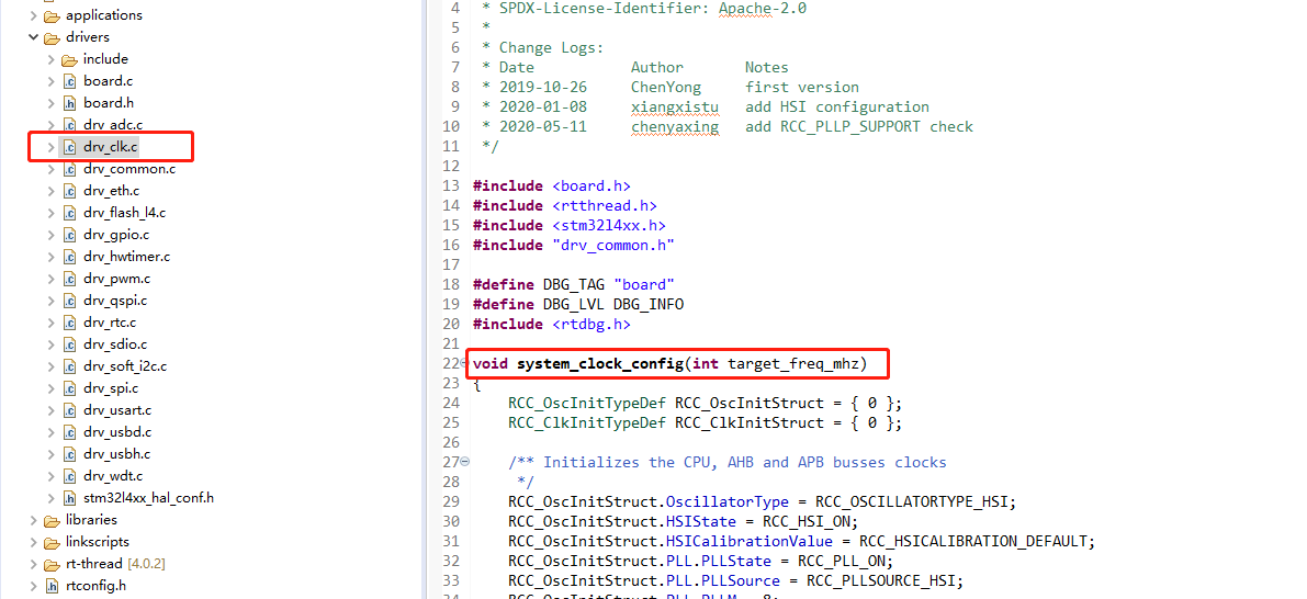
- Copy the system clock initialization function
void SystemClock_Config(void)inmain.cfile in the project generated by CubeMx. - Replace the system clock configuration function
void system_clock_config(int target_freq_mhz)indrv_clk.cfile in the project generated byRT-Thread Studio, as shown below:
- If using an external clock, you'll need to update the value of the corresponding external clock frequency in
stm32xxxx_hal_conf.hof the project. In the case of HSE, you need to modify the following clock frequency to the value it actually used:
```c
#define HSE_VALUE ((uint32_t)8000000U) /!< Value of the External oscillator in Hz /
```
Use Peripherals
Once the above files are configured, the ADC peripheral is ready to use, add the peripheral code in main.c.
The sample code for the use of ADC peripherals is as follows:
#include <rtthread.h>
#include "board.h"

ADC_HandleTypeDef hadc1;

/* ADC1 init function */
void MX_ADC1_Init(void)
{
  ADC_MultiModeTypeDef multimode = {0};
  ADC_ChannelConfTypeDef sConfig = {0};

  /** Common config
  */
  hadc1.Instance = ADC1;
  hadc1.Init.ClockPrescaler = ADC_CLOCK_ASYNC_DIV1;
  hadc1.Init.Resolution = ADC_RESOLUTION_12B;
  hadc1.Init.DataAlign = ADC_DATAALIGN_RIGHT;
  hadc1.Init.ScanConvMode = ADC_SCAN_DISABLE;
  hadc1.Init.EOCSelection = ADC_EOC_SINGLE_CONV;
  hadc1.Init.LowPowerAutoWait = DISABLE;
  hadc1.Init.ContinuousConvMode = DISABLE;
  hadc1.Init.NbrOfConversion = 1;
  hadc1.Init.DiscontinuousConvMode = DISABLE;
  hadc1.Init.ExternalTrigConv = ADC_SOFTWARE_START;
  hadc1.Init.ExternalTrigConvEdge = ADC_EXTERNALTRIGCONVEDGE_NONE;
  hadc1.Init.DMAContinuousRequests = DISABLE;
  hadc1.Init.Overrun = ADC_OVR_DATA_PRESERVED;
  hadc1.Init.OversamplingMode = DISABLE;
  if (HAL_ADC_Init(&hadc1) != HAL_OK)
  {
    Error_Handler();
  }
  /** Configure the ADC multi-mode
  */
  multimode.Mode = ADC_MODE_INDEPENDENT;
  if (HAL_ADCEx_MultiModeConfigChannel(&hadc1, &multimode) != HAL_OK)
  {
    Error_Handler();
  }
  /** Configure Regular Channel
  */
  sConfig.Channel = ADC_CHANNEL_3;
  sConfig.Rank = ADC_REGULAR_RANK_1;
  sConfig.SamplingTime = ADC_SAMPLETIME_2CYCLES_5;
  sConfig.SingleDiff = ADC_SINGLE_ENDED;
  sConfig.OffsetNumber = ADC_OFFSET_NONE;
  sConfig.Offset = 0;
  if (HAL_ADC_ConfigChannel(&hadc1, &sConfig) != HAL_OK)
  {
    Error_Handler();
  }

}

rt_uint32_t get_adc_value(void)
{
    HAL_ADC_Start(&hadc1);
    HAL_ADC_PollForConversion(&hadc1, 10);

    return (rt_uint32_t)HAL_ADC_GetValue(&hadc1);
}

int main(void)
{
    int count = 1;
    rt_uint32_t read_value = 0;

    MX_ADC1_Init();
    while (count++)
    {
        read_value = get_adc_value();
        rt_thread_mdelay(1000);
        rt_kprintf("adc value = %d\r\n", read_value);
    }

    return RT_EOK;
}
Compile and download the project, connect the PC2 pins of the board to the GND of the board, and the information printed from the terminal is shown as follows:

Connect the PC2 pin of the board to the 3.3V pin of the board, the information printed from the terminal is shown as follow:

As we can see from the printed results, the ADC peripheral is successfully used.
Notes
- The system clock configuration function on the
board.cfile needs to be modified according to the board. - The function
stm32xxxx_hal_msp.cis primarily to achieve the initialization of the peripheral pins and clocks, so you cannot choose to generate the.c/.hfile for each peripheral when usingCubeMxto generate configuration code for the peripheral. - When using the
CubeMxperipheral, only the actual used peripheral needs to be configured, and if the initialization function of the peripheral in thestm32xxxx_hal_msp.cfile or thedrv_spi.cfile is redefined, the initialization function of the peripheral instm32xxxx_hal_msp.cfile needs to be deleted.