PWM Device
Introduction to PWM
PWM (Pulse Width Modulation) is a method of digitally encoding the level of an analog signal. The frequency of the square wave is used to encode the level of a specific analog signal by pulses of different frequencies. The output receives a series of pulses of equal magnitude and uses these pulses to replace the device with the desired waveform.
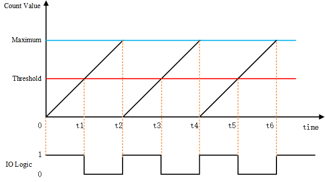
Above is a simple schematic diagram of PWM. Assuming that the timer works in a up-counter mode. When the count value is less than the threshold, it outputs a level state, such as a high level. When the count value is greater than the threshold, it outputs the opposite, such as a low level. When the count value reaches the maximum value, the counter recounts from 0 and returns to the original level state. The ratio of the high-level duration (pulse width) to the cycle time is the duty cycle, ranging from 0 to 100%. The high level of the above picture is just half of the cycle time, so the duty cycle is 50%.
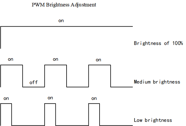
One of the common PWM control scenarios is to adjust the brightness of the light or screen. The brightness can be adjusted according to the duty cycle. The PWM adjusts the brightness not continuously, but constantly lights up and turns off the screen. When the light is turned on and off fast enough, the naked eye will always think that it is always bright. In the process of on and off, the longer the light is off, the lower the brightness of the screen to the naked eye. The longer the light is on, the less time is spent and the screen will be brighter.
Access to PWM Devices
The application accesses the PWM device hardware through the PWM device management interface provided by RT-Thread. The related interfaces are as follows:
| Function | Description |
|---|---|
| rt_device_find() | Find device handles based on the name of PWM device |
| rt_pwm_set() | Set PWM period and pulse width |
| rt_pwm_enable() | Enable PWM device |
| rt_pwm_disable() | Disable the PWM device |
Find the PWM Device
The application obtains the device handle based on the name of PWM device, which in turn can operate the PWM device. The function is as follows:
rt_device_t rt_device_find(const char* name);
| Parameter | Description |
|---|---|
| name | Device |
| Return | —— |
| Device handle | Found the corresponding device, will return the corresponding device handle |
| RT_NULL | Device not found |
In general, the name of the PWM device registered to the system is pwm0, pwm1, etc. The usage examples are as follows:
#define PWM_DEV_NAME        "pwm3"  /* name of PWM device */
struct rt_device_pwm *pwm_dev;      /* PWM device handle */
/* Search the device */
pwm_dev = (struct rt_device_pwm *)rt_device_find(PWM_DEV_NAME);
Set PWM Period and Pulse Width
Set the PWM period and duty cycle by using the following function:
rt_err_t rt_pwm_set(struct rt_device_pwm *device,
                    int channel,
                    rt_uint32_t period,
                    rt_uint32_t pulse);
| Parameter | Description |
|---|---|
| device | PWM device handle |
| channel | PWM channel |
| period | PWM period (ns) |
| pulse | PWM pulse width time (ns) |
| Return | —— |
| RT_EOK | successful |
| -RT_EIO | device is null |
| -RT_ENOSYS | Device operation method is null |
| Other Errors | Execute failed |
The output frequency of the PWM is determined by the period. For example, the time of a period is 0.5ms (milliseconds), the period value is 500000ns (nanoseconds), the output frequency is 2KHz, the duty cycle is pulse / period, and the pulse value cannot exceed period.
An example of use is as follows:
#define PWM_DEV_NAME        "pwm3"  /* name of PWM device */
#define PWM_DEV_CHANNEL      4      /* PWM channel */
struct rt_device_pwm *pwm_dev;      /* PWM device handle */
rt_uint32_t period, pulse;

period = 500000;    /* The period is 0.5ms, the unit is nanoseconds */
pulse = 0;          /* PWM pulse width value, the unit is nanoseconds */
/* Search the device */
pwm_dev = (struct rt_device_pwm *)rt_device_find(PWM_DEV_NAME);
/* Set the PWM period and pulse width */
rt_pwm_set(pwm_dev, PWM_DEV_CHANNEL, period, pulse);
Enable the PWM Device
After setting the PWM period and pulse width, you can enable the PWM device by the following function:
rt_err_t rt_pwm_enable(struct rt_device_pwm *device, int channel);
| Parameter | Description |
|---|---|
| device | PWM device handle |
| channel | PWM channel |
| Return | —— |
| RT_EOK | Enable device successful |
| -RT_ENOSYS | Device operation method is null |
| Other Errors | Enable device failed |
An example of use is as follows:
#define PWM_DEV_NAME        "pwm3"  /* name of PWM device */
#define PWM_DEV_CHANNEL      4      /* PWM channel */
struct rt_device_pwm *pwm_dev;      /* PWM device handle */
rt_uint32_t period, pulse;

period = 500000;    /* The period is 0.5ms, the unit is nanoseconds */
pulse = 0;          /* PWM pulse width value, the unit is nanoseconds */
/* Search the device */
pwm_dev = (struct rt_device_pwm *)rt_device_find(PWM_DEV_NAME);
/* Set the PWM period and pulse width */
rt_pwm_set(pwm_dev, PWM_DEV_CHANNEL, period, pulse);
/* Enable the device */
rt_pwm_enable(pwm_dev, PWM_DEV_CHANNEL);
Disable the PWM device Channel
Use the following function to turn off the corresponding channel of the PWM device.
rt_err_t rt_pwm_disable(struct rt_device_pwm *device, int channel);
| Parameter | Description |
|---|---|
| device | PWM device handle |
| channel | PWM channel |
| Return | —— |
| RT_EOK | Turn off device successful |
| -RT_EIO | Device handle is null |
| Other Errors | Turn off device failed |
An example of use is as follows:
#define PWM_DEV_NAME        "pwm3"  /* name of PWM device */
#define PWM_DEV_CHANNEL      4      /* PWM channel */
struct rt_device_pwm *pwm_dev;      /* PWM device handle */
rt_uint32_t period, pulse;

period = 500000;    /* The period is 0.5ms, the unit is nanoseconds */
pulse = 0;          /* PWM pulse width value, the unit is nanoseconds */
/* Search the device */
pwm_dev = (struct rt_device_pwm *)rt_device_find(PWM_DEV_NAME);
/* Set the PWM period and pulse width */
rt_pwm_set(pwm_dev, PWM_DEV_CHANNEL, period, pulse);
/* Enable the device */
rt_pwm_enable(pwm_dev, PWM_DEV_CHANNEL);
/* Turn off the device channel */
rt_pwm_disable(pwm_dev,PWM_DEV_CHANNEL);
FinSH Command
To set the period and duty cycle of a channel of a PWM device, use the command pwm_set pwm1 1 500000 5000. The first parameter is the command, the second parameter is the PWM device name, the third parameter is the PWM channel, and the fourth parameter is PWM period(ns), the fifth parameter is the pulse width (ns).
msh />pwm_set pwm1 1 500000 5000
msh />
To enable a channel of the PWM device, use the commandpwm_enable pwm1 1. The first parameter is the command, the second parameter is the PWM device name, and the third parameter is the PWM channel.
msh />pwm_enable pwm1 1
msh />
To disable a channel of the PWM device, use the command pwm_disable pwm1 1. The first parameter is the command, the second parameter is the PWM device name, and the third parameter is the PWM channel.
msh />pwm_disable pwm1 1
msh />
PWM Device Usage Example
The following sample code is a PWM device usage sample . The main steps of the sample code are as follows:
- Find the PWM device to get the device handle.
- Set the PWM period and pulse width.
- Enable the PWM device.
- The pulse width is modified every 50 milliseconds in the while loop.
- Connect the PWM channel to a LED, and you can see that the LED changes from dark to bright gradually, and then from bright to dark.
/*
 * Program list: This is PWM device usage example
 * The routine exports the pwm_led_sample command to the control terminal
 * Format for Command: pwm_led_sample
 * Program function: By controlling the brightness of the LED light through the PWM device,
 * you can see that the LED changes from dark to bright gradually, then from bright to dark.
 */

#include <rtthread.h>
#include <rtdevice.h>

#define PWM_DEV_NAME        "pwm3"  /* PWM device name */
#define PWM_DEV_CHANNEL     4       /* PWM channel */

struct rt_device_pwm *pwm_dev;      /* PWM device handle */

static int pwm_led_sample(int argc, char *argv[])
{
    rt_uint32_t period, pulse, dir;

    period = 500000;    /* The period is 0.5ms, the unit is nanoseconds */
    dir = 1;            /* Increase or decrease direction of PWM pulse width value */
    pulse = 0;          /* PWM pulse width value, the unit is nanoseconds*/

    /* Set LED pin mode to output */
    rt_pin_mode(LED_PIN_NUM, PIN_MODE_OUTPUT);
    /* Set high LED pin mode */
    rt_pin_write(LED_PIN_NUM, PIN_HIGH);

    /* Search the Device */
    pwm_dev = (struct rt_device_pwm *)rt_device_find(PWM_DEV_NAME);
    if (pwm_dev == RT_NULL)
    {
        rt_kprintf("pwm sample run failed! can't find %s device!\n", PWM_DEV_NAME);
        return RT_ERROR;
    }

    /* Set PWM period and pulse width defaults */
    rt_pwm_set(pwm_dev, PWM_DEV_CHANNEL, period, pulse);
    /* Enable device */
    rt_pwm_enable(pwm_dev, PWM_DEV_CHANNEL);

    while (1)
    {
        rt_thread_mdelay(50);
        if (dir)
        {
            pulse += 5000;      /* Increase 5000ns each time from 0 */
        }
        else
        {
            pulse -= 5000;      /* 5000ns reduction from the maximum */
        }
        if (pulse >= period)
        {
            dir = 0;
        }
        if (0 == pulse)
        {
            dir = 1;
        }

        /* Set the PWM period and pulse width */
        rt_pwm_set(pwm_dev, PWM_DEV_CHANNEL, period, pulse);
    }
}
/* Export to the msh command list */
MSH_CMD_EXPORT(pwm_led_sample, pwm sample);