ADC Device
An Introduction to ADC
ADC refers to analog to digital converter which is a device that converts continuously changing analog signals into discrete digital signals. Analog signals , such as temperature, pressure, sound, or images, need to be converted into digital forms that are easier to be stored, processed, and transmitted. The analog-to-digital converter can do this, and it can be found in a variety of different products. The corresponding DAC (Digital-to-Analog Converter) has a reverse conversion process compared to that of the ADC. The ADC was first used to convert wireless signals to digital signals such as television signals, or signals from long-short broadcast stations.
Conversion Process
As shown in the figure below, the analog-to-digital conversion generally involves steps of sampling, holding, quantifying, and encoding. In actual circuits, some processes are combined, such as sampling and holding, and quantization and encoding are implemented simultaneously in the conversion process.
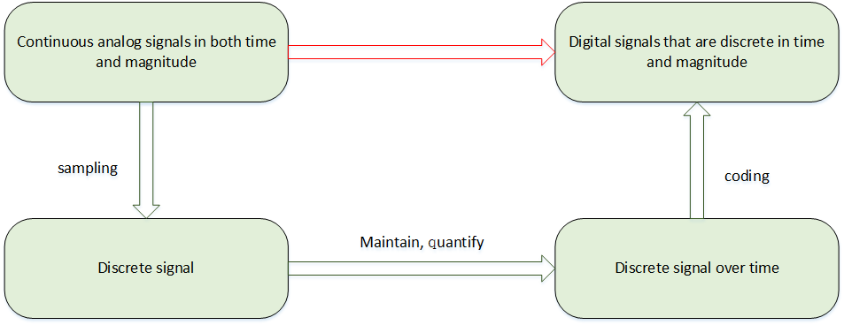
Sampling is the conversion of analog signals that changes continuously over time into time-discrete analog signals. It takes a certain amount of time for the analog signals obtained by sampling to be converted into digital signals. In order to provide a stable value for the subsequent quantization coding process, it is required to keep the sampling analog signals for a period of time after the sampling circuit.
The process of converting a numerically continuous analog quantity into a digital quantity is called quantization. Digital signals are discrete numerically. The output voltage of the sample-and-hold circuit also needs to be naturalized to a corresponding discrete level in a similar way, and any digital quantity can only be an integer multiple of a certain minimum quantity unit. The quantized value also requires the encoding process, which is the digital output of the A/D converter.
Resolution
The resolution is expressed in binary (or decimal) digits. Generally, there are 8 bits, 10 bits, 12 bits, 16 bits, etc. It explains the resolution capability of the input signals by the analog-to-digital converter. The more bits, the higher the resolution, and the more accurate the analog signal will be.
Precision
Precision represents the maximum error value between the analog and real values of the ADC devices at all numerical points, that is, the distance at which the output value deviates from the linear maximum.
Precision and resolution are two different concepts, so please pay attention to the distinction.
Conversion Rate
The conversion rate is the reciprocal of the time it takes for the A/D converter to complete an AD conversion from analog to digital. For example, an A/D converter with a conversion rate of 1MHz means that an AD conversion time is 1 microsecond.
Access ADC Device
The application accesses the ADC hardware through the ADC device management interface provided by RT-Thread. The relevant interfaces are as follows:
| Function | Description |
|---|---|
| rt_device_find() | Find device handles based on ADC device name |
| rt_adc_enable() | Enable ADC devices |
| rt_adc_read() | Read ADC device data |
| rt_adc_disable() | Close the ADC device |
Find ADC Devices
The application gets the device handle based on the ADC device name, which in turn operates the ADC device. Functions for looking for devices are as follows:
rt_device_t rt_device_find(const char* name);
| Parameter | Description |
|---|---|
| name | The name of the ADC device |
| Return | —— |
| Device handle | Finding the corresponding device will return to the corresponding device handle |
| RT_NULL | No device found |
In general, the names of the ADC device registered to the system are adc0, adc1, etc., and an usage example is as follows:
#define ADC_DEV_NAME        "adc1"  /* ADC device name */
rt_adc_device_t adc_dev;            /* ADC device handle */
/* find the device */
adc_dev = (rt_adc_device_t)rt_device_find(ADC_DEV_NAME);
Enable ADC Channel
Before reading the ADC device data, Use the following function to enable the device:
rt_err_t rt_adc_enable(rt_adc_device_t dev, rt_uint32_t channel);
| Parameter | Description |
|---|---|
| dev | ADC device handle |
| channel | ADC channel |
| Return | —— |
| RT_EOK | Succeed |
| -RT_ENOSYS | Failed, the device operation method is empty |
| Other error code | Failed |
An usage example is as follows:
#define ADC_DEV_NAME        "adc1"  /* ADC device name */
#define ADC_DEV_CHANNEL     5       /* ADC channel */
rt_adc_device_t adc_dev;            /* ADC device handle */
/* find the device */
adc_dev = (rt_adc_device_t)rt_device_find(ADC_DEV_NAME);
/* enable the device */
rt_adc_enable(adc_dev, ADC_DEV_CHANNEL);
Read ADC Channel Sample Values
Reading the ADC channel sample values can be done by the following function:
rt_uint32_t rt_adc_read(rt_adc_device_t dev, rt_uint32_t channel);
| Parameter | Description |
|---|---|
| dev | ADC device handle |
| channel | ADC channel |
| Return | —— |
| Read values |
An example of using the ADC sampled voltage value is as follows:
#define ADC_DEV_NAME        "adc1"      /* ADC device name */
#define ADC_DEV_CHANNEL     5           /* ADC channel */
#define REFER_VOLTAGE       330         /* Reference voltage 3.3V, data accuracy multiplied by 100 and reserve 2 decimal places*/
#define CONVERT_BITS        (1 << 12)   /* The number of conversion bits is 12  */

rt_adc_device_t adc_dev;                /* ADC device handle */
rt_uint32_t value;
/* find the device */
adc_dev = (rt_adc_device_t)rt_device_find(ADC_DEV_NAME);
/*  enable the device  */
rt_adc_enable(adc_dev, ADC_DEV_CHANNEL);
/* Read sampling values */
value = rt_adc_read(adc_dev, ADC_DEV_CHANNEL);
/*  Convert to the corresponding voltage value  */
vol = value * REFER_VOLTAGE / CONVERT_BITS;
rt_kprintf("the voltage is :%d.%02d \n", vol / 100, vol % 100);
The calculation formula of the actual voltage value is: sampling value * reference voltage/(1 << resolution digit). In the above example, variable vol was enlarged 100 times, so finally the integer part of voltage is obtained through vol / 100, and the decimal part of voltage is obtained through vol % 100.
Close the ADC Channel
Use the following function can close the ADC channel :
rt_err_t rt_adc_disable(rt_adc_device_t dev, rt_uint32_t channel);
| Parameter | Description |
|---|---|
| dev | ADC device handle |
| channel | ADC channel |
| Return | —— |
| RT_EOK | Succeed |
| -RT_ENOSYS | Failed, the device operation method is empty |
| Other error code | Failed |
An example:
#define ADC_DEV_NAME        "adc1"  /* ADC device name */
#define ADC_DEV_CHANNEL     5       /* ADC channel */
rt_adc_device_t adc_dev;            /* ADC device handle */
rt_uint32_t value;
/* find the device */
adc_dev = (rt_adc_device_t)rt_device_find(ADC_DEV_NAME);
/* enable the device */
rt_adc_enable(adc_dev, ADC_DEV_CHANNEL);
/* read sampling values */
value = rt_adc_read(adc_dev, ADC_DEV_CHANNEL);
/*  convert to the corresponding voltage value */
vol = value * REFER_VOLTAGE / CONVERT_BITS;
rt_kprintf("the voltage is :%d.%02d \n", vol / 100, vol % 100);
/* close the channel */
rt_adc_disable(adc_dev, ADC_DEV_CHANNEL);
FinSH Command
Before using the device, you need to find out whether the device exists. You can use the command adc probe followed by the name of the registered ADC device. As follows:
msh >adc probe adc1
probe adc1 success
A channel of the enabled device can use the command adc enable followed by the channel number.
msh >adc enable 5
adc1 channel 5 enables success
To read data from a channel of an ADC device, you can use the command adc read followed by the channel number.
msh >adc read 5
adc1 channel 5  read value is 0x00000FFF
msh >
To close a channel of an ADC device, you can use the command adc disable followed by the channel number.
msh >adc disable 5
adc1 channel 5 disable success
msh >
ADC Device Usage Example
The specific usage of the ADC device can refer to the following sample code. The main steps of the sample code are as follows:
- First find the device handle based on the ADC device name “adc1”.
- After the device is enabled, read the sample value of the corresponding channel 5 of the adc1 device, and then calculate the actual voltage value with the resolution of 12 bits and the reference voltage of 3.3V.
- Finally close the corresponding channel of the ADC device.
Running result: Print the raw and converted data which actually read , and print the calculated actual voltage value.
/*
 * Program Listing: ADC Device Usage Routines
 * The routine exports the adc_sample command to the control terminal
 * adc_sample Command call format: adc_sample
 * Program function: The voltage value is sampled by the ADC device and converted to a numerical value.
 *                   The sample code reference voltage is 3.3V and the number of conversion bits is 12 bits.
*/

#include <rtthread.h>
#include <rtdevice.h>

#define ADC_DEV_NAME        "adc1"      /* ADC device name */
#define ADC_DEV_CHANNEL     5           /* ADC channel */
#define REFER_VOLTAGE       330         /* Reference voltage 3.3V, data accuracy multiplied by 100 and reserve 2 decimal places*/
#define CONVERT_BITS        (1 << 12)   /* The number of conversion bits is 12 */

static int adc_vol_sample(int argc, char *argv[])
{
    rt_adc_device_t adc_dev;
    rt_uint32_t value, vol;
    rt_err_t ret = RT_EOK;

    /* find the device */
    adc_dev = (rt_adc_device_t)rt_device_find(ADC_DEV_NAME);
    if (adc_dev == RT_NULL)
    {
        rt_kprintf("adc sample run failed! can't find %s device!\n", ADC_DEV_NAME);
        return RT_ERROR;
    }

    /* enable the device */
    ret = rt_adc_enable(adc_dev, ADC_DEV_CHANNEL);

    /* read sampling values */
    value = rt_adc_read(adc_dev, ADC_DEV_CHANNEL);
    rt_kprintf("the value is :%d \n", value);

    /* convert to the corresponding voltage value */
    vol = value * REFER_VOLTAGE / CONVERT_BITS;
    rt_kprintf("the voltage is :%d.%02d \n", vol / 100, vol % 100);

    /* close the channel */
    ret = rt_adc_disable(adc_dev, ADC_DEV_CHANNEL);

    return ret;
}
/* export to the msh command list */
MSH_CMD_EXPORT(adc_vol_sample, adc voltage convert sample);