RT-Thread Studio-based Serial Driver Development Document
Introduction
When you create an RT-Thread project using RT-Thread Studio, the serial driver is automatically added to the project, and the user does not need to manually add the source code associated with the serial drive, which makes it easy to use the serial port for input and output. At the same time, RT-Thread Studio has a graphical configuration interface that helps to change the serial interface configuration more concise, users do not need to change and drive the relevant source code, only need to change or add related macros, the following introduction will be based on the stm32l475-atk-pandora development board, which will cover the Nano and full versions of RT-Thread respectively.
RT-Thread Nano serial driver development
The use of Nano serial drivers is mainly used for the input and output of the console.
Configure the default serial port
Use RT-Thread Studio to create a Nano project, as shown in the following image.
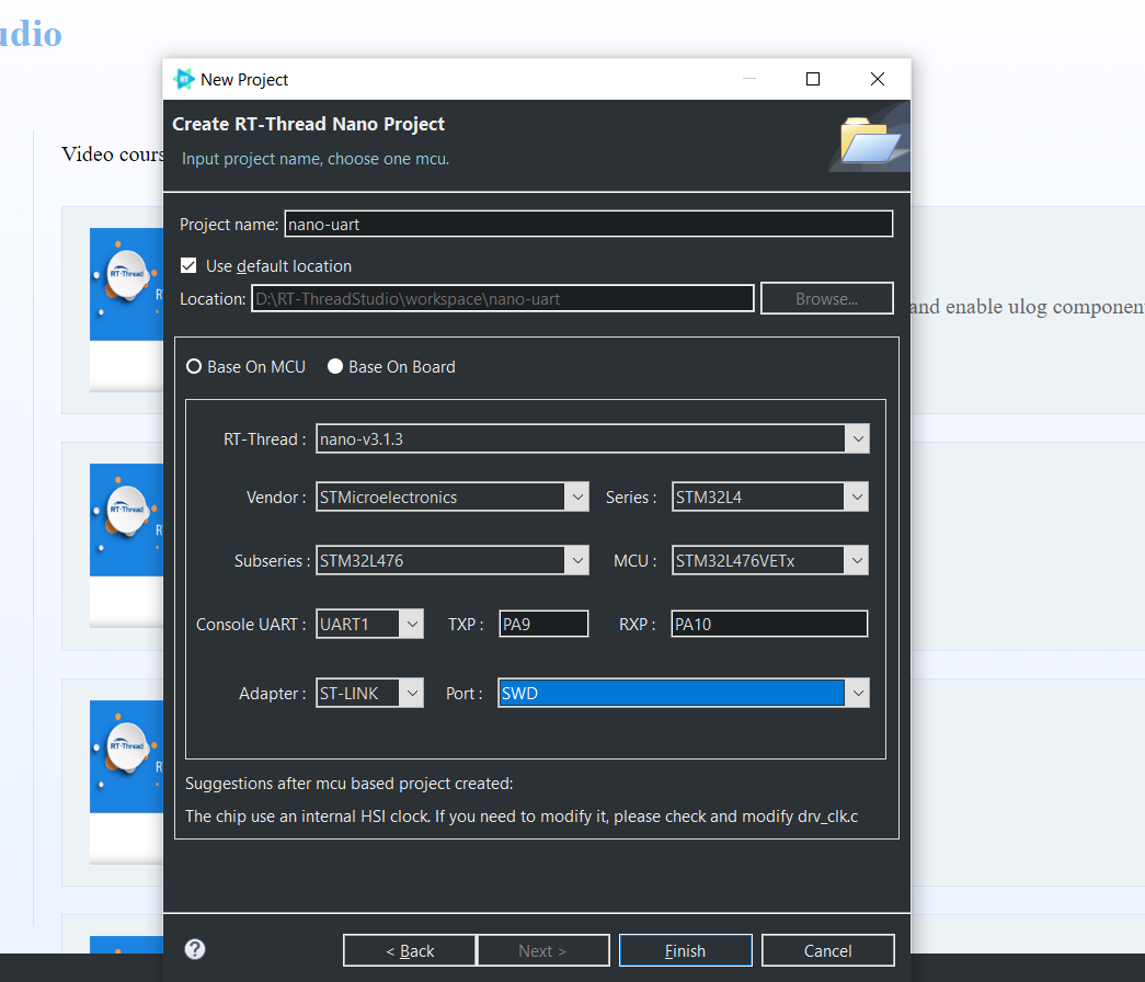
The configuration process can be summarized as follows:
- Define your own project name and the storage path for the generated project files.
- Select 'Base on MCU' to create a project and select the RT-Thread Nano version.
- Select the vendor and chip series.
- Configure serial information.
- Configure the debugger information.
Once the project is configured, click the 'Finish' button to create the RT-Thread project. main.c file in the RT-Thread project will automatically generate the following code:
int main(void)
{
    int count = 1;

    while (count++)
    {
        LOG_D("Hello RT-Thread!");
        rt_thread_mdelay(1000);
    }

    return RT_EOK;
}
After compiling and downloading the project, open the serial tool in RT-Thread Studio can view the print information for the serial output, as shown below:

You can see the information from the serial output that we have successfully used the serial output to print the information.
Modify the default serial
As we can learn in the last section, the RT-Thread Studio graphical interface successfully configured the serial output, but some actual applications may need to use additional serial output information, which can be achieved by modifying some macro definitions.
Modify board.h macro
The board stm32l475-atk-pandora using UART1 to output by default, if change to UART2 (TX->PA2、RX->PA3), the 5 macros of serial port 1 in board.h
#define BSP_USING_UART1
#define BSP_UART1_TX_PIN       "PA9"
#define BSP_UART1_RX_PIN       "PA10"
should change to the macros of serial port 2, as shown in the following:
#define BSP_USING_UART2
#define BSP_UART2_TX_PIN       "PA2"
#define BSP_UART2_RX_PIN       "PA3"
The modification of macro definition is divided into 2 main aspects.
- Modify the macro definitions corresponding to the serial port, such as
BSP_USING_UART1、BSP_USING_UART2and so on. - Modify the ports used by serial
TX/RX, such as"PA2"、"PA3"etc.
Use the modified serial output
After modifying the macro on the board.h, compile, and download it. Use the USB cable to connect the pins of PA2, and PA3, and open the RT-Thread Studio serial tool, the log of the serial output as shown below.

The output information shows that the console switched to serial 2 and the information is successfully output.