RT-Thread Studio-based PIN Device Application Documentation.
Introduction
In general, MCU has many pins for users, and RT-Thread provides PIN device drivers that abstract these GPIO pins into a PIN device that the application can access through the PIN device management interface. PIN device drivers have the following characteristics:
- Number each pin in the PIN drive file, unlike the number method in the chip manual. When used, the PIN device can be operated with a PIN in the PIN driver.
- Pin input/output mode can be set, pin-level status can be read/set, pin break callback function can be set, etc.
When you create a project based in RT-Thread Standard Version by using RT-Thread Studio, RT-Thread's PIN device is turned on by default, so users can use the PIN device directly without reconfiguring or modifying the source code.
Create RT-Thread Standard Version Project
Using RT-Thread Studio to create an RT-Thread v4.0.2 project, as shown below:
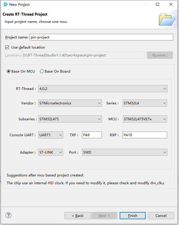
The configuration process can be summarized as follows:
- Define your own project name and the storage path for the generated project files.
- Select 'Base on MCU' to create a project and select RT-Thread version v4.0.2.
- Select the vendor and chip series.
- Configure serial information.
- Configure the debugger information.
Once the project is configured, click the 'Finish' button to create the RT-Thread project.
Use PIN Device
In the project that created based on the RT-Thread Standard Version, the following definition is automatically generated in the main.c function.
#define LED0_PIN    GET_PIN(A, 5)

int main(void)
{
    int count = 1;
    /* set LED0 pin mode to output */
    rt_pin_mode(LED0_PIN, PIN_MODE_OUTPUT);

    while (count++)
    {
        /* set LED0 pin level to high or low */
        rt_pin_write(LED0_PIN, count % 2);
        LOG_D("Hello RT-Thread!");
        rt_thread_mdelay(1000);
    }

    return RT_EOK;
}
Using a PIN driver requires using GET_PIN to obtain the corresponding PIN, when the PIN is obtained, functions such as rt_pin_write can be used to operate the pin. For example, the LED of the stm32l475-atk-pandora board is connected to PE7, so it is modified to
#define LED0_PIN GET_PIN(E, 7)
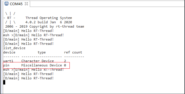
Compile and download the code and you can see the LED on the board flashing in every 1000 ms. Entering the list_device command in the terminal you can observe that the pin device has been successfully registered in the system, as shown in the following ../image.
For more instructions on the use of PIN devices, please refer to HERE.