RT-Thread Studio-based ETH Driver Development Document
Introduction
RT-Thread introduces a network device framework to make it easier for developers to develop network applications, while RT-Thread also offers a wide range of network component packages for developers to quickly develop their own network applications.
This article will take the stm32f407-atk-explorer board as an example to introduce how to use RT-Thread Studio to add Ethernet drivers and lwIP protocol stacks.
The ETH device driver development can be summarized as follows:
- Create an RT-Thread Standard Version project.
- Defines
BSP_USING_ETHandPHYrelated macros inboard.h. - Initialize
ETHrelated pins and clocks inboard.c. - Open HAL Library support for ETH in
stm32xxxx_hal_config.h. - Implement
PHYreset function inboard.c. - Configure the
lwIPprotocol stack.
For more details about ETH configuration and addition processes please refer to the introduction of the ETH in the corresponding project file board.h.
Create RT-Thread Project
Using RT-Thread Studio to create an RT-Thread v4.0.2 project, as shown below:

The configuration process can be summarized as follows:
- Define your own project name and the storage path for the generated project files.
- Select 'Base on MCU' to create a project and select RT-Thread version v4.0.2.
- Select the vendor and chip series.
- Configure serial information.
- Configure the debugger information.
Once the project is configured, click the 'Finish' button to create the RT-Thread project.
Define ETH Related Macros
Navigate to the ETH configuration instructions in board.h, define the related macros of BSP_USING_ETH and PHY according to the comments, in this case, the on-board Ethernet PHY chip we are using is LAN8720A, so the related macros of ETH are defined as follows:
#define BSP_USING_ETH
#ifdef BSP_USING_ETH
#define PHY_USING_LAN8720A
#endif
Initialize Pins and Clocks
Once the BSP_USING_ETH macro is defined, the drv_eth.c file will start compiling, this file has only simply configured how the ETH works and function transfers, the initialization of the clock and pins for ETH peripheral needs the help of the code generated in STM32CubeMx.
For example, the initialization code for ETH generated by STM32CubeMx (typically stored in the stm32_xxxx_hal_msp.c file) needs to be copied to the bottom of the board.c file of your own project for compiling, as shown below:
void HAL_ETH_MspInit(ETH_HandleTypeDef* heth)
{
  GPIO_InitTypeDef GPIO_InitStruct = {0};
  if(heth->Instance==ETH)
  {
  /* USER CODE BEGIN ETH_MspInit 0 */

  /* USER CODE END ETH_MspInit 0 */
    /* Peripheral clock enable */
    __HAL_RCC_ETH_CLK_ENABLE();

    __HAL_RCC_GPIOC_CLK_ENABLE();
    __HAL_RCC_GPIOA_CLK_ENABLE();
    __HAL_RCC_GPIOG_CLK_ENABLE();
    /**ETH GPIO Configuration
    PC1     ------> ETH_MDC
    PA1     ------> ETH_REF_CLK
    PA2     ------> ETH_MDIO
    PA7     ------> ETH_CRS_DV
    PC4     ------> ETH_RXD0
    PC5     ------> ETH_RXD1
    PG11     ------> ETH_TX_EN
    PG13     ------> ETH_TXD0
    PG14     ------> ETH_TXD1
    */
    GPIO_InitStruct.Pin = GPIO_PIN_1|GPIO_PIN_4|GPIO_PIN_5;
    GPIO_InitStruct.Mode = GPIO_MODE_AF_PP;
    GPIO_InitStruct.Pull = GPIO_NOPULL;
    GPIO_InitStruct.Speed = GPIO_SPEED_FREQ_VERY_HIGH;
    GPIO_InitStruct.Alternate = GPIO_AF11_ETH;
    HAL_GPIO_Init(GPIOC, &GPIO_InitStruct);

    GPIO_InitStruct.Pin = GPIO_PIN_1|GPIO_PIN_2|GPIO_PIN_7;
    GPIO_InitStruct.Mode = GPIO_MODE_AF_PP;
    GPIO_InitStruct.Pull = GPIO_NOPULL;
    GPIO_InitStruct.Speed = GPIO_SPEED_FREQ_VERY_HIGH;
    GPIO_InitStruct.Alternate = GPIO_AF11_ETH;
    HAL_GPIO_Init(GPIOA, &GPIO_InitStruct);

    GPIO_InitStruct.Pin = GPIO_PIN_11|GPIO_PIN_13|GPIO_PIN_14;
    GPIO_InitStruct.Mode = GPIO_MODE_AF_PP;
    GPIO_InitStruct.Pull = GPIO_NOPULL;
    GPIO_InitStruct.Speed = GPIO_SPEED_FREQ_VERY_HIGH;
    GPIO_InitStruct.Alternate = GPIO_AF11_ETH;
    HAL_GPIO_Init(GPIOG, &GPIO_InitStruct);

  /* USER CODE BEGIN ETH_MspInit 1 */

  /* USER CODE END ETH_MspInit 1 */
  }

}
Open Support for ETH in HAL Library
Open support for ETH in stm32_xxxx_hal_config.h file, which means cancel off the HAL_ETH_MODULE_ENABLED macro definition comments, as shown below:
#define HAL_ETH_MODULE_ENABLED
Implement PHY Reset Function
The phy_reset function is called in drv_eth.c file, which needs to be implemented according to your own situation, in this case, the PHY reset pin is connected to the PD3 pin, so the implementation of the reset function is as follows:
#include <rtdevice.h>
#define RESET_IO GET_PIN(D, 3)

void phy_reset(void)
{
    rt_pin_mode(RESET_IO, PIN_MODE_OUTPUT);
    rt_pin_write(RESET_IO, PIN_HIGH);
    rt_thread_mdelay(50);
    rt_pin_write(RESET_IO, PIN_LOW);
    rt_thread_mdelay(50);
    rt_pin_write(RESET_IO, PIN_HIGH);
}
Notes:
Different PHY chip has different reset methods and needs to be implemented according to the actual situation of the specific board.
Configure lwlp Protocol Stack
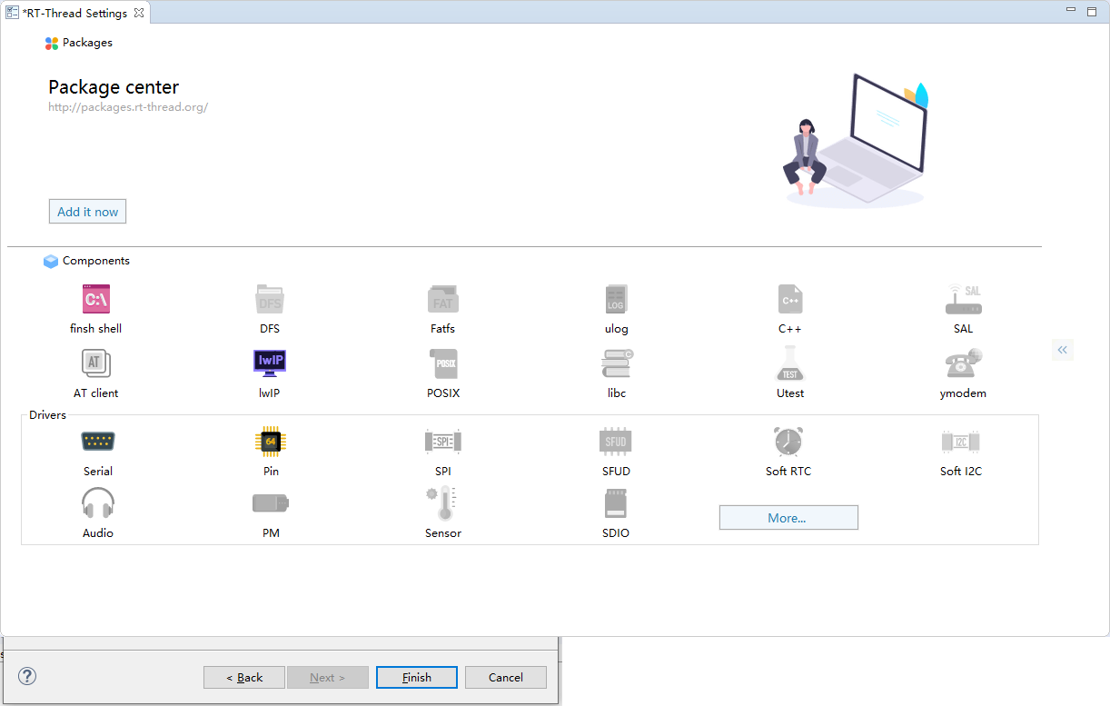
In RT-Thread Settings, left-click lwIP in the graphical configuration interface to enable the lwIP stack (the component will be enabled and its icon lights up), as shown below:
Right-click lwIP there is an option to view its 'details configuration', as shown below:
RT-Thread Settings
---- Component
--------Network
------------Lightweight TCP/IP Stack
Configuration results are shown as below:
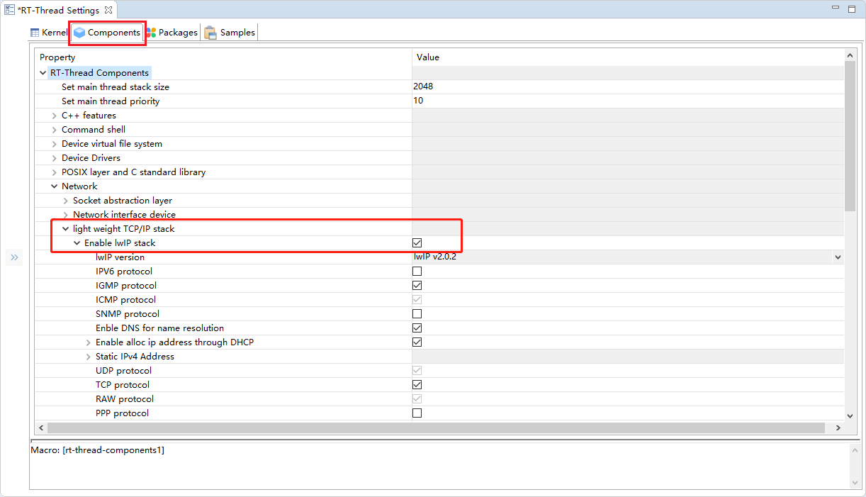
In this example, the lwIP stack is configured by default. You can modify it according to your requirements.
Use Network
After ETH and lwIP are configured, compile the download program, and open the serial terminal tool, enter the following network test commands:
ping www.baidu.com
The output information of the terminal is as follows:

As can be seen from the image above, the board has successfully connected to the network.
Notes
- For more instructions on the use of RT-Thread Network, please refer to Network Introduction and SAL Introduction.